PCB Fiducial Marks: Global and Local Alignment Guidelines
MOZPCB Editorial Team (PCB manufacturing guides) · Updated 2026/11/13
PCB fiducial marks are recognizable features, commonly exposed circular copper targets, that a solder-paste printer or placement machine uses to locate and orient a board or panel. They connect the physical workpiece to the coordinate system used by the assembly program.
Good fiducial planning covers more than drawing a copper circle. The target must remain visible after fabrication, accessible while the board is clamped, distinguishable from nearby features, and consistent with the released panel and placement data. This guide describes the decisions to agree with your assembler without imposing one machine’s dimensional rules on every line.
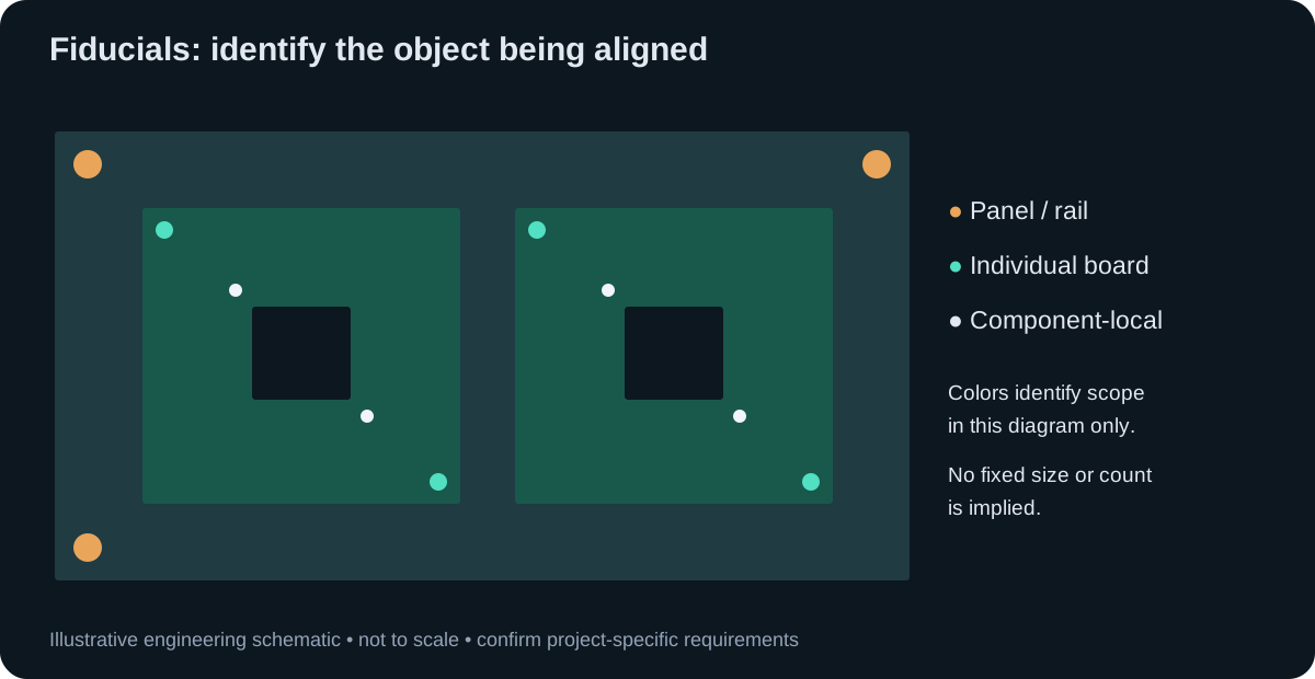
Panel, board and local fiducials: which object is being aligned?
Global usually means marks that locate a whole workpiece, but a panelized job contains both a panel and individual boards. Some suppliers call the marks on each board local, while others reserve local for targets around a component. Name the object being aligned in your drawing so the terminology cannot change the build intent.
| Scope | What it references | Question for the assembler |
|---|---|---|
| Panel fiducials | The full array, often using targets on handling rails | Can the printer and placement machine see these while the panel is clamped? |
| Board fiducials | Each individual circuit inside the array | Does the process need per-board correction for the supplied panel? |
| Component-local fiducials | A limited region near a placement-critical package | Does package accuracy or board behavior justify local correction? |
How many marks are needed, and where should they go?
One point can locate a position but cannot by itself establish board rotation. Two distinct points define a baseline; an additional non-collinear reference adds geometric information that a capable system may use to check or correct alignment. The actual correction model depends on the machine and program.
Distribute global targets across the usable workpiece rather than clustering them in one corner. Widely separated references generally make orientation less sensitive to a fixed target-location error. Avoid a layout that could be mistaken for a rotated or mirrored panel, and identify each target unambiguously in the assembly data.
Eurocircuits, for example, specifies at least three panel-frame fiducials for its process and recommends individual board targets on multi-board panels. That is a published supplier rule, not a universal MOZPCB minimum. Confirm count and placement with the intended assembly equipment.
Do not add component-local marks to every package by default. They consume area and may not be used by the program. Conversely, omitting them because a nominal pitch seems large enough is not a reliable rule. Provide the actual package, land pattern, board size and placement accuracy needs for review.
Copper, mask and paste must describe the same optical target
A common fiducial uses a round copper target with a mask opening that leaves the target exposed. The surrounding area must provide sufficient optical separation from other copper, legend, parts and edges. Define the target diameter, mask opening and surrounding keepout as separate dimensions.
Exclude paste from the target so the printer does not deposit solder over the reference feature. Do not silently turn a fiducial into a test point: probe marks, solder or handling damage may alter the optical surface. If a shared feature is proposed, have the assembler approve its use.
A solid target should not contain an unapproved drill or via. A tooling hole locates a board mechanically; a fiducial locates it optically. The two can coexist but should not be substituted based only on approximate position. Review the mask and paste layer guide when exporting these features.
Set edge clearance from the handling envelope
The visible board edge is not the only boundary. Conveyor clamps, support tooling, component overhangs and the vision field can block a target that appears clear in CAD. Ask for the machine handling envelope and measure clearance from the correct reference: target center, copper edge or mask-opening edge, as specified.
Rails can provide room for global targets, but a rail added after layout changes the panel origin and array offsets. Decide who owns panelization before releasing the fabrication package. If the fabricator proposes the panel, require an approved panel drawing that carries the targets through to the assembly program.
On a double-sided assembly, review target visibility and orientation for each side. State how the bottom side is viewed and how the coordinate system is transformed; do not manually mirror a file that the machine software already mirrors.
Fiducial and placement-file release checklist
Review the copper, mask, paste and panel outline together, then compare the target coordinates with the placement export. A mark visible on a PDF but absent from copper artwork will not be fabricated.
| Check | Release evidence |
|---|---|
| Identification and scope | Target IDs classified as panel, board or component-local |
| Shape and dimensions | Approved copper target, mask opening and keepout geometry |
| Surface access | No paste, legend or unapproved holes on the target; handling clearance confirmed |
| Array and origin | Panel revision, board offsets, units and coordinate origin agreed |
| Each assembled side | Top/bottom target visibility and viewing/rotation convention confirmed |
| Population data | Fiducials identified as reference features, not components to procure or place |
| Change ownership | Approval required for moving targets, changing rails or modifying the array |
Troubleshooting: the marks exist, but alignment still fails
If every board is displaced by the same amount, compare origin, panel offsets and selected references before changing the artwork. If rotation or mirroring is wrong, check viewing conventions and target identification. If only one board in an array is affected, review per-board coordinates and local alignment rather than applying a global offset to every board.
If recognition is intermittent, inspect the target surface, mask opening, neighboring features, contamination and clamp access. More fiducials do not fix a dirty target or contradictory coordinate files. Ask for the machine’s observed failure and the corresponding target ID so the design team can review the exact feature.
What to send for SMT alignment review
Send the single-board files, proposed panel drawing, fiducial coordinates and dimensions, BOM/CPL, assembly sides, component overhangs and any placement-critical packages. Ask SMT assembly to confirm target requirements and tooling access before bare-board manufacture.
A useful note is: “Panel revision [ID]; assembled sides [top/bottom]; targets [IDs and scope]; coordinate origin and viewing convention [definition]; copper diameter [value], mask opening [value], keepout [value]; assembler approval of clamping and recognition required before release.” Each value must come from the accepted design/process.
Frequently asked questions
Are PCB fiducials just silkscreen circles?
Do fiducials need solder paste?
Can panel marks replace board marks?
What is the standard fiducial size?
Are fiducials needed on both sides?
Sources
- Fiducials — assembly guidelines — Eurocircuits
Related articles
- PCB Assembly2026/11/13 · 6 min
What Is SMT? Components, Process and Assembly Decisions
Understand SMT, SMD and PCBA, then connect component packages to land patterns, placement data, soldering and inspection requirements.
Read article - PCB Assembly2026/07/08 · 5 min
SMT vs Through-Hole Assembly: Process and Cost Differences
When surface-mount wins, when through-hole still matters, and how mixed-technology boards sequence SMT, wave, and selective solder without yield surprises.
Read article - PCB Assembly2026/11/02 · 7 min
PCB Assembly Process: BOM Review, Placement, Reflow and Test
Understand the SMT and through-hole assembly flow, its inspection gates and the files needed to define a build that can actually be accepted.
Read article - PCB Assembly2026/10/13 · 4 min
Turnkey PCBA RFQ Checklist
Everything a turnkey PCB assembly quote request needs—fabrication data, BOM and sourcing notes, assembly instructions, and test requirements—in one reviewable package.
Read article