Flexible PCB Manufacturing Services
Flexible circuits replace bulky cables and let electronics bend, fold, and fit where rigid boards cannot. MOZPCB builds single-sided, double-sided, and multilayer flex PCBs with engineering review on every quote.
Service overview
Flexible PCBs (FPCs) are built on polyimide films instead of rigid laminate, which makes material selection—film thickness, adhesive versus adhesiveless copper, coverlay system—the first driver of both reliability and cost. We confirm those choices against your bend geometry before quoting.
Like our rigid-flex work, every flex quote includes a review of whether your bends are static (fold once at installation) or dynamic (repeated motion), since dynamic applications need thinner copper, adhesiveless constructions, and neutral-axis routing.
Typical programs range from a simple single-layer jumper replacing a wire harness to multilayer flex with controlled impedance for camera modules and display interconnects.
What we offer
- Single-sided, double-sided, and multilayer flexible circuits
- Adhesiveless polyimide constructions for tight bends and dynamic flexing
- Coverlay processing with defined openings, dams, and windowing
- Stiffeners in polyimide, FR-4, and stainless steel per your drawings
- ZIF connector tails with controlled thickness and gold plating
- EMI shielding films and silver paste shielding when specified
- Flex PCB assembly including fixturing and carrier panels for SMT
- DFM feedback on trace routing near bends, pad anchors, and tear stops
Technical capabilities
- Polyimide film thicknesses commonly 12.5, 25, and 50 micron, per stackup review
- Copper weights from 1/3 oz rolled-annealed copper for dynamic bends up to 2 oz
- Minimum bend radius guidance: roughly 6–10x thickness for static, 100x for dynamic bends
- Impedance-controlled flex layers when materials and stackup support the target
- Selective plating, gold fingers, and button plating subject to design review
- Panelization with tab routing suited to downstream flex assembly
Common applications
- Wearables, hearables, and fitness devices with curved enclosures
- Camera modules, displays, and antenna interconnects in compact devices
- Medical sensors, catheter and probe electronics, and patient-worn monitors
- Battery management and folded interconnects in dense assemblies
- Automotive interior electronics where vibration rules out connectors
How the process works
- 01
Requirements intake
Share Gerber, BOM, drawings, quantities, and any reliability or compliance notes.
- 02
Technical alignment
We confirm materials, finishes, assembly flow, and test expectations with you.
- 03
Production & inspection
Manufacturing and assembly follow the agreed traveler with documented checks.
- 04
Delivery
Packing, labeling, and shipment according to your logistics instructions.
In our factory
-
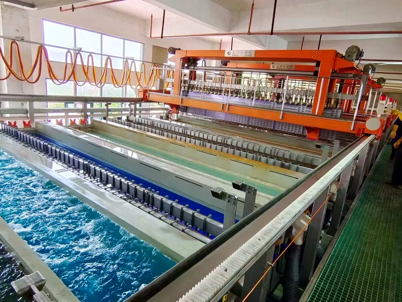
Plating line -
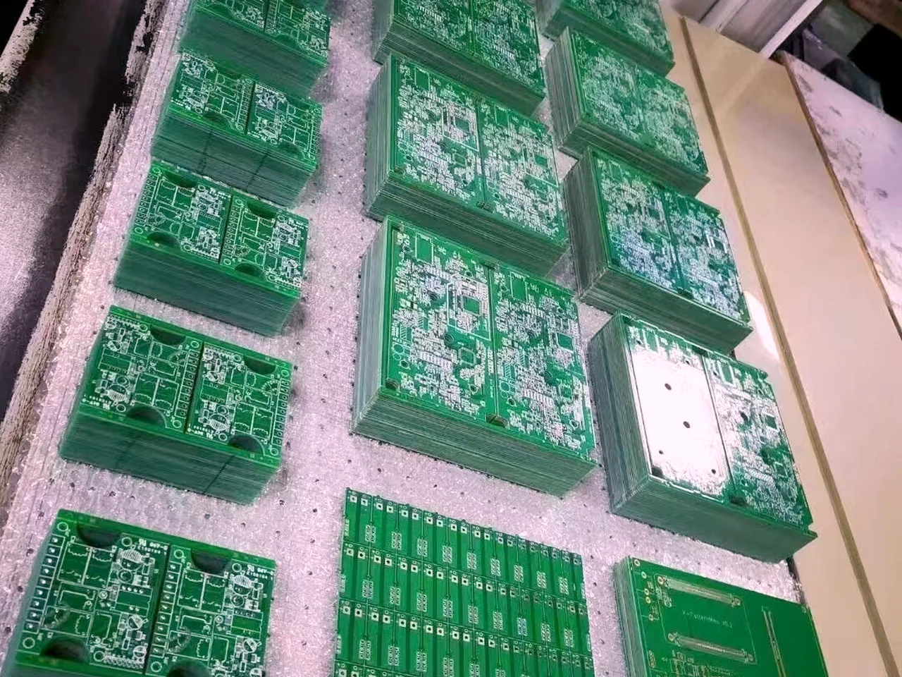
Panelized boards -
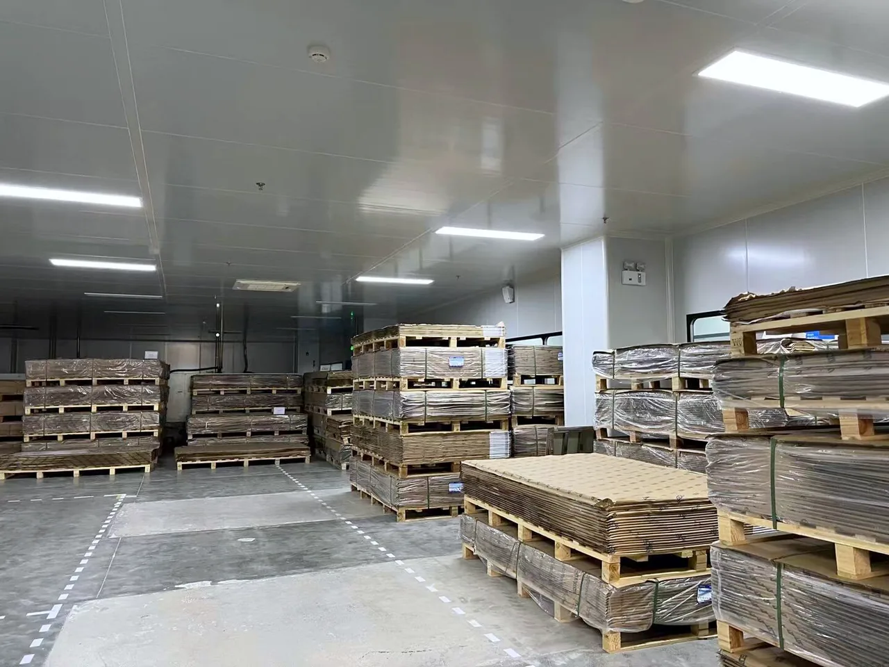
Laminate store
Related services
FAQ
When should I use a flex PCB instead of a rigid board with cables?
What is the difference between adhesive and adhesiveless flex materials?
Do flex PCBs support fine-pitch component assembly?
How do you specify bend requirements in an RFQ?
Can flex circuits include shielding for EMI-sensitive signals?
Get started
Ready for the next step?
Send your project files and requirements. We will review stackup, assembly, and test needs, then respond with a clear quotation path.